Iranian Classification Society Rules

< Previous | Contents | Next >
Section 23 Automatic and Remote Control Systems
2301. Application
1. The requirements of this Section apply to tests and inspection for the type approval of the auto- matic and remote control systems (device, units and sensors, etc) including basic softwares(if any) for use in the marine environment in accordance with the requirements in Pt 6, Ch 2, 301. 1 of the Rules. However, fire detection system and gas detection system are to comply with the follow- ing requirements.
(1) Fire detection system is to comply with the EN 54 series or equivalent standard.
(2) Design requirements and performance tests
tection of fixed/portable combustible gases standard. However audible alarm level and A.830(19).
(3) Gas detection system for oxygen detection
for gas detection system for measurement and de-
are to comply with IEC 60079-29-1 or equivalent signal characteristics are to comply with IMO Res.
and measurement is to comply with the EN 50104
or equivalent standard, However audible alarm level and signal characteristics are to comply with IMO Res. A.830(19).
2. Hardwares and softwares for marine navigational and radio-communication equipment and systems are to be comply with the requirements of this Section and in addition, attention is to be paid to the requirements of KS X IEC 60945.
2302. Data to be submitted
The following reference data are to be submitted to the Society in addition to those specified in
102.
1. General
(1) All documentation shall provide relevant information in a clear and unambiguous manner..
(2) Symbols and abbreviations used shall be explained, or referenced to an appropriate international standard or code recognized by the Society.
2. Hardware
(1) System block diagram, showing the arrangement, input and output devices and interconnections
(2) Wiring diagram (electrical systems), piping diagram (pneumatic or hydraulic
(3) Details of input and output devices
(4) Details of power supplies
3. System functional description
(1) System specifications
(2) System performance for normal or abnormal equipment operation.
(3) Instructions for normal and abnormal operating modes;
(4) Transfer of control
(5) Redundancy or reversionary mode
(6) Test facilities
(7) Failure detection and identification facilities (automatic and manual)
(8) Data security
(9) Access restriction
(10) Special aspects requiring user attention.
(11) In addition, documentation shall be provided concerning procedures for:
(a) start-up
(b) restoration of functions
(c) maintenance and periodical testing
(d) data back-up
(e) software reload and system regeneration
(f) failure location and repair
systems)
4. Software
(1) Quality plan
(2) Software shall be fully described, e.g.:
(a) a description of the basic software installed in each hardware unit;
(b) a description of the communication software installed on nodes in a network;
Guidance for Approval of Manufacturing Process and Type Approval, Etc. 2015 139
![]()
(c) descriptions of application software (not program listings);
(d) tools for system set-up and process equipment configuration.
(3) The description of application software shall include, e.g.:
(a) information of system modules that must be operative in order to maintain functions includ- ing dependencies on other systems;
(b) detail of each module at a level sufficient to understand its function;
(c) relationship between the software modules that must be operative in order to maintain each function;
(d) data and control flow between software modules;
(e) configuration of the software, including priority schemes;
(f) switching mechanisms for redundant systems.
(4) A schedule of anticipated equipment operation ranges and limits for alarm and safety functions
shall be provided.
5. User interface
(1) Control station design and arrangement shall be detailed including drawings, dimensions, pic- tures, etc. of each user input or output device at a level sufficient to asses the working principles.
(2) Details of screen-based computer dialogue shall be produced, including:
(a) description of the functions allocated to each input device;
(b) details of individual screen views, e.g. schematics, colour photos, etc.;
(c) description of menu operation.
6. Failure analysis for safety related functions only is to be carried out using appropriate means such as FMEA and the results are to be submitted to the Society,
2303. Type test report
Upon completion of the type test, the manufacturer is to submit to the Society the complete test report including test conditions, test results and required information.
2304. Type test
1. Hardware
(1) General
(A) Tests are to be carried out under following atmosphere conditions, rated electrical source
voltage and rated electrical source frequency unless otherwise specified.
(a) temperature : 25 ± 10 ℃
(b) relative humidity : 60 ± 30 %
(c) atmospheric pressure : 96 kPa ± 10 kPa
(B) Measuring and testing equipment used in the type test are to be calibrated in accordance with the related standards and/or codes.
(C) The number of EUT(Equipment Under Test) is, as a rule, to be one for each type.
However, additional EUT may be required when deemed necessary by the Society.
(D) Raising and lowering rate of temperature is to be within 1℃/min (mean value for 5 mi-
nutes) unless otherwise specified.
(E) Power supply variation test and pressure test are applied on pneumatic and hydraulic type equipment only.
(F) Flame retardant test is to be generally applied by manufacturer's option to demonstrate that plastic components of the equipment under test with a large mass are flame retardant and self-extinguishing under the influence of flame.
(2) Test methods and criteria
(A) After the drawings and documents submitted in accordance with the requirements in 2302. have been examined, tests are to be carried out in accordance with the testing condition and method of Table 3.23.1 in the presence of the Society's surveyor, and they are to be pro- ven to satisfy the criteria of Table 3.23.1.
(B) Where tests which do not fully comply with the testing condition and method, and the cri-
teria of Table 3.23.1, they may comply with a standard deemed appropriate by the Society such as IEC, Korean Industrial Standards(KS), etc.
140 Guidance for Approval of Manufacturing Process and Type Approval, Etc. 2015
![]()
2. Software
(1) Module tests
Software module tests are to provide evidence that each module performs its intended function and does not perform unintended functions.
(2) Subsystem tests
Subsystem testing is to verify that modules interact correctly to perform the intended functions and do not perform unintended functions.
(3) System test
System testing is to verify that subsystems interact correctly to perform the functions in accord- ance with specified requirements and do not perform unintended functions.
3. Performance tests
(1) Integration tests
Programmable electronic system integration testing is to be carried out using satisfactorily tested system software, and as far as practicable intended system components.
(2) Fault simulation
Faults are to be simulated as realistically as possible to demonstrate appropriate system fault de- tection and system response. The results of any required failure analysis are to be observed.
Guidance for Approval of Manufacturing Process and Type Approval, Etc. 2015 141
![]()
Table 3.23.1 Environmental Test Items, Testing Conditions and Methods, and Criteria
No. | Test item | testing condition and method | Criteria |
1 | Visual inspection | · Examine the external, structure, etc., of the equipment. | · The equipment comply with the specifications. |
2 | Performance test | · Check the operation of the equipment. · Check the self monitoring features if provided. · Check the specified protection against an access to the memory. · check against the effect of unerroneous use of control el- ements in the case of computer systems. | · The equipment operates sat- isfactory. |
3 | Electrical power supply failure test | · Check the operation of the equipment when the electrical power supply is interrupted 3 times during 5 minutes. (interruption time is 30 seconds each time) - The time of 5 minutes may be exceeded if the equip- ment under test needs a longer time for start up, e.g. booting sequence. For equipment which requires booting, one additional power supply interruption during booting to be performed · Check the possible corruption of programme or data held in programmable electronic systems (where applicable) | · The equipment operates sat- isfactory without manual cali- bration after restoration of the electrical power supply. |
4 | Electrical power supply variation test | · Check the operation of the equipment when the electrical power supply varies as shown in the following AC supply DC supply | · No abnormality is observed. The equipment operates sat- isfactory. |
Combination | Voltage variation permanent (%) | Frequency variation permanent (%) |
1 | +6 | +5 |
2 | +6 | -5 |
3 | -10 | -5 |
4 | -10 | +5 |
voltage transient (%) | frequency transient (%) | |
1.5 sec | 5 sec | |
5 | +20 | +10 |
6 | -20 | -10 |
For the equipment not related to a battery (%) | Voltage tolerance continuous | ±10 |
Voltage cyclic variation | 5 | |
Voltage ripple | 10 | |
For the equipment related to a battery (%) | For the equipment connected to a battery during charging | -25 ~ +30 |
For the equipment not connected to a battery during charging | -25 ~ +20 |
142 Guidance for Approval of Manufacturing Process and Type Approval, Etc. 2015
![]()
![]()
Table 3.23.1 Environmental Test Items, Testing Conditions and Methods, and Criteria
No. | Test item | testing condition and method | Criteria |
5 | Power supply variation test | · Check the operation of the equipment when the pneumatic and the hydraulic power supplies are maintained continuously +20 % and -20 % of the working pressure for at least 15 minutes. | · No abnormality is observed. · The equipment operates satisfactory. |
6 | Dry heat test | · The test shall be carried out at 25 ±2 ℃ in atmospheric temperature. · The absolute humidity shall not exceed 20 g of water va- por per cubic meter of air(corresponding approximately to 50 % relative humidity at 35℃). · Test A : The equipment is at an operating condition and apply the environmental condition of +70 ±2 ℃ for 2 hours. And check the operation of the equipment during the last 1 hour at the test temperature and after recovery. · Test B : For the equipment installed in air conditioned spaces, the environmental condition of +55 ±2 ℃ for 16 hours may be applied. Check the operation of the equip- ment during the last 1 hour at the test temperature and after recovery. Where the equipment is attached with other equipments in the console and housing, test A is to be performed. · Detailed test methods are referred to Test Bb or Test Bd of IEC 60068-2-2.
Note (*) Raising and lowering rate of temperature is to be within 1°C/min.(mean value for a period within 5 minutes Fig 3.23.1 Program of dry heat test | · No abnormality is observed. · The equipment operates satisfactory. |
7 | Damp heat test | - The temperature in the chamber shall be continuously raised to 55 ±2 ℃ during 3h±30 min. During this period, the rel- ative humidity shall be not less than 95 %, except during the last 15min when it shall be not less than 90 %. (see Fig 3.23.2) - The temperature shall then be maintained 55 ±2 ℃ until 12h ±30 min from the start of the cycle. During this period, the relative humidity shall be 93±3%, except for the first and last 15 min when it shall be between 90% and 100%. - 2 cycles shall be carried out as shown in Fig 3.10.2. The equipment is kept under operating condition during complete 1st cycle and switched off during 2nd cycle except for the operation test. And check the operation of the equipment during the first 2 hours of the 1st cycle at the environ- mental condition, during the last 2 hours of 2nd cycle at the environmental condition and after recovery. | · No abnormality is observed. · The equipment operates satisfactory. |
Guidance for Approval of Manufacturing Process and Type Approval, Etc. 2015 143
![]()
![]()
Table 3.23.1 Environmental Test Items, Testing Conditions and Methods, and Criteria (continued)
No. | Test item | Testing condition and method | Criteria |
7 | Damp heat test | - Insulation resistance measurements are carried out before and af- ter test. - Detailed test methods are referred to Test Db of IEC 60068-2-30.
Fig 3.23.2 Program of damp heat test | No abnormality is observed. The equipment operates satisfactory. |
8 | Vibration test | The equipment is at an operating condition and apply the sweeping of vibration specified in the following over the frequency range of 2(+3, -0) Hz ~ 100 Hz in order to find resonance points.(points of which amplification factor : Q≥2 are considered resonance points.) Frequency Amplitude or Acceleration 2(+3, -0) ~ 13.2 Hz Amplitude ±1.0 mm 13.5 ~ 100 Hz Acceleration ±0.7 g When resonance points do not exist, apply the vibration of acceleration ±0.7 g at 30 Hz for 90 minutes as an endurance test. When resonance points exist, repeat the test with necessary provisions to avoid resonance or apply the vibration (same amplitude or acceleration of resonance point) at the resonance frequency for 90 minutes as an endurance test. However, where sweep test is to be carried out instead of the discrete frequency test and a number of resonant frequencies is detected close to each other, duration of the test is to be 120 min. Sweep over a restricted frequency range between 0.8 and 1.2 times the critical frequencies can be used where appropriate. Critical frequency is a frequency at which the equipment being tested may exhibit: - malfunction and/or performance deterioration - mechanical resonances and/or other response effects occur, e.g. chatter during the vibration test, functional tests are to be | No abnormality is observed. The equipment operates satisfactory. |

144 Guidance for Approval of Manufacturing Process and Type Approval, Etc. 2015
![]()
![]()
Frequency | Amplitude or Acceleration |
2(+3, -0) ~ 25.0 Hz | Amplitude ±1.6 mm |
25.0 ~ 100 Hz | Acceleration ±4.0 g |
Table 3.23.1 Environmental Test Items, Testing Conditions and Methods, and Criteria (continued)
No. | Test item | Testing condition and method | Criteria |
8 | Vibration test (continued) | · The test is carried out in three axis direction. · It is recommended as guidance that Q does not exceed 5. · For the equipment intended to be installed in severe vi- bration conditions such as diesel engines, air com- pressors, the vibration level specified in the following is applied. · More severe conditions may exist for example on ex- haust manifolds of diesel engines especially for medium and high speed engine. Values may be required to be in these cases 40 Hz to 2000 Hz- acceleration ±10.0
at 600 ℃ duration 90 minutes. · Detailed test methods are referred to Test Fc of IEC | |
9 | Inclination test | · The equipment is at an operating condition and check the operation of the equipment with 22.5° static inclination. · The equipment is at an operating condition and check the operation of the equipment with rolling of 22.5° at period of about 10 seconds for not less than 15 min. · The test is carried out in three axis directions. · These inclination tests are normally not required for equipment with no moving parts. · Detailed test methods are referred to KS C IEC 60092- 504. | No abnormality is observed. · The equipment operates sat- isfactory. |
10 | Insulation resistance test | · Measure the insulation resistance between current carry- ing parts and between current parts and earth when measured with the following application voltage. · Measurements are carried out before and after; other series of environmental tests, damp heat test, cold test and salt mist test. · For the equipment containing circuits in which the ap- plication of the test voltage is not desirable, the test voltage is applied after removing the circuits. | The insulation resistance (M ) is not less than the value specified in the following. |
11 | High voltage test | · Apply the following test voltage, alternating of a fre- quency of 50 Hz or 60 Hz, between current carrying parts and between current-carrying parts connected and earth for 1 minute. Un · For the equipment containing circuits in which the ap- plication of the test voltage is not desirable, the test voltage is applied after removing the circuits. |
Rated voltage : Un(V) | Test voltage(V) |
Un ≤ 65 | 2 × Un, min. 24 |
Un > 65 | 500 |
Rated voltage | Before test | After test |
Un≤65 | 10 | 1.0 |
Un>65 | 100 | 10 |
Rated voltage : Un(V) | Test voltage(V) |
≤ 65 | 2 × Un + 500 |
65 < Un ≤ 250 | 1,500 |
250 < Un ≤ 500 | 2,000 |
500 < Un ≤ 690 | 2,500 |
Guidance for Approval of Manufacturing Process and Type Approval, Etc. 2015 145
![]()
![]()
Table 3.23.1 Environmental Test Items, Testing Conditions and Methods, and Criteria (continued)
No. | Test item | Testing condition and method | Criteria |
12 | Cold test | · The test shall be carried out at 25 ±10 ℃ in atmospheric temperature. · The equipment is switched off except for the operation test and apply the environmental condition of +5 ±3 ℃ for 2 hours. And check the operation of the equipment during the last hour at the test temperature and after recovery. · For the equipment installed in open decks, etc., the environ- mental condition of -25 ±3 ℃ is applied for 2 hours. · Insulation resistance measurements are carried out before and after cold test. · Detailed test methods are referred to Test Ab or Test Ad of IEC 60068-2-1.
Fig 3.23.3 Program of cold test | · No abnormality is observed. · The equipment operates satisfactory. |
13 | (2) Salt mist test | · The equipment is switched off except when its operation is checked. Apply four cycles of the environmental condition of spraying NaCl liquid (saline solution, 5 % NaCl, pH 6.5 ~ 7.2, 20 ±2 ℃) for 2 hours and leaving for 7 days. Check the operation of the equipment during the 7th day of each cycle and after recovery. · Damp chamber conditions for storage are to be maintained as follows; - Temp. : 40℃±2℃ - Relative humidity : 93% +2% -3% · the test is carried out according to the following procedure - Insulation resistance and functional test before test - Functional test on the 7th day of each cycle period - Insulation resistance and functional test : 4 to 6 hours af- ter recovery · Detailed test methods are referred to Test Kb of IEC 60068-2-52. | · No abnormality is observed. · The equipment operates satisfactory. |
14 | Electrostatic discharge immunity test | · Check the operation of the equipment when the electrostatic discharge immunity test is carried out according to the fol- lowing condition. · The test is to be confined to the points and surfaces that can normally be reached by the operator. · Detailed test methods are referred to Level 3 of KS C IEC 61000- 4-2. | · Performance (2) Criterion B |
Contact discharge | 6 kV |
Air discharge | 8 kV |
Interval between single discharge | 1 sec. |
No. of Pulses | 10 per polarity |
146 Guidance for Approval of Manufacturing Process and Type Approval, Etc. 2015
![]()
![]()
Frequency range | 80 MHz ~ 2 GHz |
Modulation | 80 % AM at 1,000 Hz |
Field strength | 10 V/m |
Frequency sweep rate | -3 ≤1.5 × 10 decades/sec. (or 1 %/3 sec.) |
Table 3.23.1 Environmental Test Items, Testing Conditions and Methods, and Criteria (continued)
No. | Test item | Testing condition and method | Criteria |
15 | Radiated radio frequency immunity test | · Check the operation of the equipment when the radiated ra- dio frequency immunity test is carried out according to the following condition. · If for tests of equipment an input signal with a modulation frequency of 1,000 Hz is necessary, a modulation fre- quency(80 % AM) of 400 Hz may be chosen. · The test is to be confined to the appliances exposed to direct radiation by transmitters at their place of installation. · Detailed test methods are referred to Level 3 of KS C IEC 61000-4-3. | · Performance (3) Criterion A |
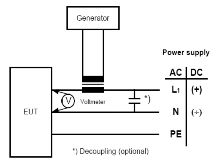
16 | Conducted low frequency immunity test | · Check the operation of the equipment when the conducted low frequency immunity test is carried out according to the following condition. (values in round brackets are shown where the rated frequency of the equipment is 50 Hz)
Fig 3.23.4 Test Set-up - Conducted Low Frequency Test · In case of marine navigational and radiocommunication equipment and systems, this test can be exempted. | · Performance (3) Criterion A |
Frequency range | 60 ~12 kHz (50 ~10 | ||
Test voltage | AC | 10 % of supply voltage | 60 Hz~900 Hz (50 Hz~750 Hz) |
10 % to 1 % of supply voltage | 900 Hz~6 Hz (750 Hz~5 kHz) | ||
1 % of supply voltage | 6 kHz~12 kHz (5 kHz~10 kHz) | ||
DC | 10 % of supply voltage (at least 3 V) | 50 Hz~10 kHz | |
Maximum power | AC | min 3 V r.m.s, max 2 W. | |
DC | 2 W | ||
Guidance for Approval of Manufacturing Process and Type Approval, Etc. 2015 147
![]()
![]()
Frequency range | 150 kHz ~ 80 MHz |
Modulation | 80 % AM at 1,000 Hz |
Amplitude | 3 Vrms |
Frequency sweep rate | -3 ≤ (or 1 %/3 sec.) |
Single pulse time | 5 nS (10 ~ 90 % value) |
Single pulse width | 50 nS (50 % value) |
Amplitude(peak) | line on power supply port/earth : 2 kV |
line/line on I/O data control and signal lines : 1 kV | |
Pulse period | 300 mS |
Burst duration | 15 mS |
Duration | 5 min./polarity |
Table 3.23.1 Environmental Test Items, Testing Conditions and Methods, and Criteria (continued)
No. | Test item | Testing condition and method | Criteria |
17 | Conducted high frequency immunity test | · Check the operation of the equipment when the con- ducted high frequency immunity test is carried out ac- cording to the following condition. 1.5 × 10 decades/sec. · If for tests of equipment an input signal with a modu- lation frequency of 1 kHz is necessary a modulation frequency(80 % AM) of 400 Hz should be chosen. · Detailed test methods are referred to Level 2 of KS C IEC 61000-4-6. | (3) · Performance Criterion A |
18 | Burst/Fast transient immunity test | · Check the operation of the equipment when the burst fast transient immunity test is carried out according to the following condition. · Detailed test methods are referred to Level 3 of KS C IEC 61000-4-4. | (2) · Performance Criterion B |
19 | Surge immunity test | · Check the operation of the equipment when the surge immunity test is carried out according to the following condition. · Detailed test methods are referred to Level 2 of KS C IEC 61000-4-5. | (2) · Performance Criterion B |
20 | Radiated emission test | · Radiated emission test is to be carried out according to the following.
For equipment installed in the bridge and deck zone. | · Radiated emission is to be within limits in the table. |
Pulse rise time | 1.2 (10 ~ 90 % value) |
Pulse width | 50 50 % value) |
Amplitude(peak) | line/earth :1 kV |
line/line : 0.5 kV | |
Repetition rate | at least 1 pulse/min. |
No. of pulse | 5 per polarity |
Frequency range | Limits |
150 kHz~ 300 kHz | 80 ~ 50 dB V m |
300 kHz ~ 30 MHz | 50 ~ 34 dB V m |
30 MHz ~ 2,000 MHz | 54 dB V m |
156 MHz ~ 165 MHz | 24 dB V m |
148 Guidance for Approval of Manufacturing Process and Type Approval, Etc. 2015
![]()
![]()
Frequency range | Limits |
150 kHz ~ 30 MHz | 80~50 dB V m |
30 MHz~100 MHz | 60~54 dB V m |
100 MHz~2,000 MHz | 54 dB V m |
156 MHz~165 MHz | 24 ddB V m |
Frequency range | Limits |
10 kHz ~ 150 kHz | 96 ~ 50 dB V |
150 kHz ~ 350 kHz | 60 ~ 50 dB V |
350 kHz ~ 30 MHz | 50 dB V |
Frequency range | Limits |
10 kHz ~ 150 kHz | 120 ~ 69 dB V |
150 kHz ~ 500 kHz | 79 dB V |
500 kHz ~ 30 MHz | 73 dB V |
Table 3.23.1 Environmental Test Items, Testing Conditions and Methods, and Criteria (continued)
No. | Test item | Testing condition and method | Criteria |
20 | Radiated emission test |
For equipment installed in a zone other than bridge and deck zone · Distance between equipment and antenna is to be 3 m · Detailed test methods are referred to CISPR 16-1, 2 | · Radiated emission is to be within limits in the table. |
21 | Conducted emission test | · Conducted emission test is to be carried out according to the following.
For equipment installed in the bridge and deck zone. For equipment installed in a zone other than bridge and deck zone · Detailed test methods are referred to CISPR 16-1, 2 | · Conducted emission is to be within limits in the table. |
22 | Flame resistance test | · Flame resistance test is to be carried out according to the following condition. · The test is performed with the EUT or housing of the EUT applying needle-flame test method. · Detailed test methods are referred to KS C IEC 60092-101 or IEC 60695-11-5 | - The burnt out or damaged part of the specimen by not more than 60 mm long. - No flame, no incandescence or - In the event of a flame or incandescence being present, it shall extinguish itself within 30 s of the removal of the needle flame without full combustion of the test specimen. - Any dripping material shall extinguish itself in such a way as not to ignite a wrapping tissue. The drip height is 200 mm ± 5 mm. |
23 | Pressure test | · Apply the pneumatic or hydraulic pressure of 1.5 times the designed pressure. | · No abnormality is observed. |
(Note) (1) Salt mist test is to be carried out for equipment installed in weather exposed areas. (2) Performance Criterion B: The Equipment Under Test is to continue to operate as intended after the tests. No degradation of performance or loss of function is allowed as defined in the technical specification published by the manufacturer. During the test, degradation or loss of function or performance which is self recoverable is however allowed but no change of actual operating state or stored data is allowed. (3) Performance Criterion A: The EUT is to continue to operate as intended during and after the test. No degradation of performance or loss of function is allowed as defined in the technical specification published by the manufacturer. | |||
Flame application | 5 times 15 sec. each |
Interval between each application | 15 sec. or 1 time 30 sec. |
Guidance for Approval of Manufacturing Process and Type Approval, Etc. 2015 149
![]()
![]()